Wiring an Ethernet cable correctly comes down to two things: putting the eight wires in the right color order, and knowing whether you need a straight-through or a crossover cable. This guide explains RJ45 color coding for straight and crossover cables — the T568A and T568B standards, the exact pin colors, and when to use each cable type.
Why RJ45 Color Coding Matters
An RJ45 connector has eight pins, and an Ethernet cable has eight wires arranged in four twisted pairs. For a link to work reliably, each wire must land on the correct pin, with the pairs kept intact. Getting the color order wrong is the number-one reason Ethernet cables fail — and because the fault is inside the connector, it is invisible from the outside. Following a standard color code is how you guarantee the transmit and receive pairs line up correctly between devices.
The Two Wiring Standards: T568A and T568B
There are two recognized color-code standards, defined under TIA/EIA-568. Both use the same eight wires; they simply arrange two of the pairs differently. What matters is consistency — you pick one standard and use it correctly at each end depending on the cable type.
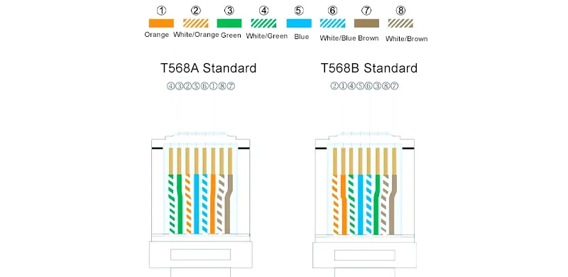
T568B Color Order (Pins 1–8)
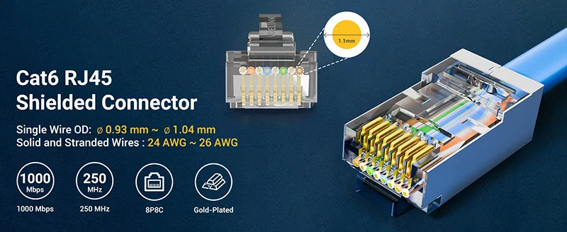
T568B is the most widely used standard in many regions:
- Pin 1: White/Orange
- Pin 2: Orange
- Pin 3: White/Green
- Pin 4: Blue
- Pin 5: White/Blue
- Pin 6: Green
- Pin 7: White/Brown
- Pin 8: Brown
T568A Color Order (Pins 1–8)
T568A swaps the orange and green pairs compared with T568B:
- Pin 1: White/Green
- Pin 2: Green
- Pin 3: White/Orange
- Pin 4: Blue
- Pin 5: White/Blue
- Pin 6: Orange
- Pin 7: White/Brown
- Pin 8: Brown
Notice that only pins 1, 2, 3, and 6 differ between the two standards — the blue and brown pairs stay in the same positions.
Straight-Through vs Crossover: The Key Difference
The cable type is decided by which standard you use at each end.
Straight-Through Cable
A straight-through cable uses the same standard on both ends — T568B to T568B, or T568A to T568A. This is the everyday patch cable used to connect a device to a switch, router, or wall outlet. In the vast majority of installations, this is the cable you make.
Crossover Cable
A crossover cable uses T568A on one end and T568B on the other. This swaps the transmit and receive pairs, historically allowing two similar devices to connect directly — computer to computer, switch to switch, or router to router — without a hub or switch between them.
Straight-Through vs Crossover at a Glance
| Cable Type | End 1 | End 2 | Used To Connect |
| Straight-through | T568B | T568B | Device to switch/router/wall outlet |
| Straight-through | T568A | T568A | Device to switch/router/wall outlet |
| Crossover | T568A | T568B | Like device to like device (PC-PC, switch-switch) |
Keeping the Twists Right
Color order is only half of a good termination; keeping the twisted pairs intact is the other half. Ethernet relies on each pair staying twisted almost all the way to the connector, because the twists are what cancel interference and allow high-speed signaling. If you untwist the pairs too far back while arranging the colors, you introduce crosstalk that a cable might survive at 100 Mbps but fail at Gigabit or 10 Gigabit speeds — and a wiremap test can still show a “pass” because the wires are in the right order even though performance is compromised. The practical rule is to untwist no more than about a centimeter, arrange the colors quickly, and let the twists run as close to the plug as possible. This is also why the standards keep specific pairs together on adjacent pins: following the color code correctly naturally preserves the pairing that the twists depend on.
Do You Still Need Crossover Cables?
In practice, crossover cables are far less common than they used to be. Most modern equipment supports Auto-MDI/MDI-X, which automatically detects and adapts the transmit and receive pairs, so a straight-through cable works even between two similar devices. As a result, straight-through is the default choice for nearly all new installations, and crossover cables mostly appear when working with older gear that lacks auto-detection.
Straight-Through in Everyday Use
It is worth emphasizing how dominant the straight-through cable is in practice. Almost every cable you plug in at home or in an office — connecting a computer, printer, IP camera, game console, or smart TV to a switch, router, or wall outlet — is a straight-through cable with the same standard on both ends. Patch cords sold ready-made are wired this way, and structured cabling from wall outlets back to the patch panel is terminated to a single consistent standard throughout. Understanding this saves a lot of second-guessing: unless you are deliberately connecting two like devices directly on older equipment, you want a straight-through cable, and the only decision is which single standard to apply consistently at both ends. Keeping that default in mind turns most terminations into a simple, repeatable routine and reserves the crossover pattern for the rare cases that genuinely need it.
Which Standard Should You Choose?
Either T568A or T568B works, provided you are consistent. T568B is the more common choice in many commercial installations, while some government and residential wiring specifies T568A. The important rules are: use the same standard throughout a single project to avoid confusion, and for a straight-through cable, match the standard on both ends. Mixing standards unintentionally on a straight-through cable creates an accidental crossover that may not work as expected.
How to Read the Color Code on the Connector
When you crimp an RJ45, you hold the connector with the clip facing away from you and the pins facing up, then read the wires left to right as pins 1 through 8. This orientation matters, because it is easy to reverse the order and create a mirror-image termination that fails. A useful habit is to lay the untwisted wires flat in the correct color sequence before inserting them, check the order against your chosen standard, trim them evenly, and only then slide them into the plug — confirming through the clear connector body that each colored wire still sits in its correct position all the way to the tip. Because the two standards differ only in the orange and green pairs, a common real-world error is starting one end on T568B and absentmindedly finishing the other end the same way you would a crossover; verifying the color order at both ends before crimping prevents this.
Verify Your Wiring
Whatever color code you use, always confirm the result with a network cable tester. A wiremap tester checks that every wire lands on the correct pin in the right order and flags opens, shorts, reversed pairs, crossed pairs, and split pairs. Because a wiring error is invisible from the outside, testing is the only reliable way to prove the color coding is correct before the cable goes into service.
Get the Right Termination Tools
Accurate color coding is easier with quality tools. Aevumix supplies RJ45 crimping tools, cable strippers, termination tools, and network cable testers for building and verifying Ethernet cables, alongside a full range of fiber optic tools and test equipment. If you would like help choosing the right termination and testing tools, contact our team.
FAQs
What Is the RJ45 Color Code for a Straight-Through Cable?
Use the same standard on both ends. For T568B, the order is White/Orange, Orange, White/Green, Blue, White/Blue, Green, White/Brown, Brown — identical at each end.
What Is the Difference Between T568A and T568B?
They swap the orange and green pairs. Only pins 1, 2, 3, and 6 differ; the blue and brown pairs stay in the same positions. Both are valid — consistency is what matters.
How Do I Make a Crossover Cable?
Wire one end to T568A and the other end to T568B. This swaps the transmit and receive pairs, allowing two similar devices to connect directly without a switch or hub.
Do I Still Need Crossover Cables?
Usually not. Most modern devices support Auto-MDI/MDI-X, which adapts the pairs automatically, so a straight-through cable works even between similar devices. Crossover cables are mainly needed for older equipment.
Which Wiring Standard Is Better, T568A or T568B?
Neither is technically better; both perform identically. T568B is more common in many commercial settings, while T568A appears in some government and residential wiring. Choose one and use it consistently across a project.