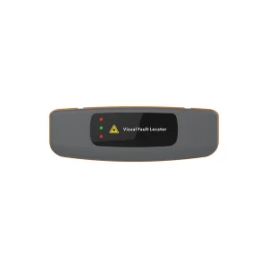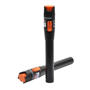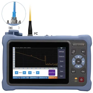
A visual fault locator, or VFL, is one of the simplest and most useful tools in fiber optic work — a handheld device that shines a bright red laser down a fiber so you can see problems with your own eyes. This guide explains how to use a visual fault locator, what it can and cannot find, and the safety rules that go with it.
What a Visual Fault Locator Does
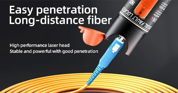
A VFL launches a visible red laser (typically around 650 nm) into an optical fiber. Where the fiber is intact, the light stays in the core; where there is a break, a sharp bend, a bad splice, or a faulty connector, light escapes and glows red at that point through the fiber coating or jacket. It also lets you confirm continuity and check polarity. Because the light is visible, the VFL turns invisible faults into something you can literally point to — making it the go-to tool for the “last mile” that an OTDR cannot resolve.
What a VFL Is Good For
- Locating breaks: a break or crack glows red at the fault point.
- Finding sharp bends and macrobends: light escapes where the fiber is bent too tightly.
- Checking connectors and splices: a bad connector or splice leaks visible light.
- Confirming continuity: red light emerging at the far end means the fiber is continuous.
- Verifying polarity and tracing fibers: identifying which fiber is which in a bundle or patch panel.
- Short-distance faults: finding faults inside the OTDR “dead zone” near the connector, which an OTDR cannot see.
How to Use a Visual Fault Locator: Step by Step
Step 1: Inspect and Clean the Connector
Before connecting, inspect and clean the fiber connector you will plug into the VFL. A dirty connector scatters light and can give misleading results.
Step 2: Connect the Fiber to the VFL
Most VFLs have a universal 2.5 mm connector that accepts SC, ST, and FC connectors, with an adapter for 1.25 mm LC connectors. Insert the fiber connector into the VFL’s output port.
Step 3: Turn On the Laser
Switch the VFL on, choosing continuous-wave (steady) or pulse (blinking) mode. Pulse mode is often easier to spot in bright conditions and can be gentler on the eyes.
Step 4: Inspect Along the Fiber
Walk the fiber and look for red light glowing out at any point. A glow indicates a break, crack, sharp bend, or bad splice/connector at that spot. Pay special attention to connectors, splice trays, and anywhere the cable is bent.
Step 5: Check the Far End
Look at the far end of the fiber. Steady red light emerging there confirms continuity through the link. No light at the far end — combined with a glow somewhere along the run — pinpoints the fault location.
Step 6: Interpret and Act
Mark the fault location, then repair it — re-terminate a connector, redo a splice, or relieve a bend — and re-check with the VFL to confirm the fault is gone.
VFL Safety: Never Look Into the Beam
The VFL emits a real laser, so eye safety is essential. Never look directly into the VFL output port or into the end of a fiber connected to a VFL — the concentrated laser light can damage your eyes. Treat every fiber as if it could be energized, and view fibers indirectly (against a surface) rather than staring into the end face. These precautions apply even though the light is visible.
Continuous vs Pulse Mode
Most visual fault locators offer two output modes, and knowing when to use each helps. In continuous-wave mode the laser stays on steadily, which is best for tracing a fiber, checking continuity, and identifying which fiber is which in a bundle or patch panel. In pulse (blinking) mode the light flashes at a few hertz, which is often easier to see when hunting a faint leak in bright ambient light and can be a little easier on the eyes. A common workflow is to start in continuous mode to confirm continuity and get a steady view of the whole run, then switch to pulse mode when looking closely for a subtle glow at a suspected bend or connector. Neither mode changes what the VFL fundamentally does — it simply makes the escaping light easier to spot under different conditions — so experiment with both when a fault is hard to pin down.
VFL vs OTDR: They Work Together
| Feature | Visual Fault Locator | OTDR |
| How it finds faults | Visible red light escaping | Backscatter/reflection analysis |
| Range | Short (typically up to ~5–10 km) | Long (many km) |
| Near-end “dead zone” | Excellent — sees close faults | Blind spot near the connector |
| Cost/complexity | Low, simple, handheld | Higher, needs interpretation |
| Output | Visual glow you point to | Detailed trace with distances |
The VFL shines exactly where the OTDR is blind — in the first few meters and at the fiber ends — which is why technicians carry both.
Common VFL Applications in the Field
A few everyday scenarios show why the VFL earns its place in the kit. When a patch cord fails, a quick VFL check instantly reveals whether the break is inside a connector or along the cord, saving a guess-and-replace cycle. During splicing, shining a VFL through a freshly made splice confirms light is passing and reveals a bad splice glowing at the tray. When commissioning a patch panel, the VFL identifies exactly which port a fiber lands on by lighting up the correct connector. And when an OTDR reports a fault very close to the near end — inside its dead zone — the VFL steps in to find it visually. In each case the value is the same: the VFL converts an invisible problem into a red glow you can point to, turning what might be an hour of tracing into a few seconds of looking. That immediacy is why it remains one of the most-used tools in fiber work despite its simplicity.
Tips for Getting Good Results
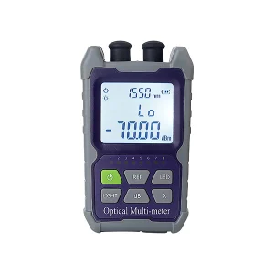
A few habits improve VFL work. Use it in a way that lets you see the coating — a glow is easier to spot on a light-colored jacket and harder through dark or armored cable. Dim the surrounding light when hunting a faint leak. Remember the range limit: a VFL is a short-range tool, so it is ideal for patch cords, splice trays, and the near end, but not for locating a fault many kilometers away. And always pair the VFL’s visual confirmation with proper testing (power meter or OTDR) when you need measured loss, not just a yes/no continuity check.
Get the Right VFL and Fiber Test Tools
A good VFL is inexpensive insurance against hours of guesswork. Aevumix supplies visual fault locators along with a full range of fiber test equipment — optical power meters, light sources, and OTDRs — plus the inspection and cleaning tools that keep results accurate. If you would like help choosing a VFL or building a fiber test kit, contact our team.
FAQs
How Do You Use a Visual Fault Locator?
Inspect and clean the connector, plug the fiber into the VFL, turn on the red laser, then look along the fiber for red light escaping at breaks, bends, or bad connectors, and check the far end for continuity. Mark and repair any fault, then re-check.
What Can a VFL Detect?
Breaks, cracks, sharp bends, bad splices and connectors, continuity, and polarity. It is especially good at short-range faults and those near the connector, inside the OTDR’s dead zone.
Is It Safe to Look at the VFL Light?
Never look directly into the VFL output or the end of a connected fiber. It emits a real laser that can damage your eyes. View fibers indirectly against a surface and treat every fiber as potentially energized.
What Is the Range of a VFL?
A VFL is a short-range tool, typically effective up to around 5 to 10 km depending on the model. For faults far down a long link, an OTDR is the right tool; the VFL excels at the near end and short cables.
Do I Still Need an OTDR if I Have a VFL?
Yes — they complement each other. The VFL gives a quick visual check and finds near-end faults the OTDR misses, while the OTDR measures loss and locates faults over long distances with a detailed trace.