If you work anywhere near fiber optic networks, you will run into the term OTDR very quickly. It appears in test reports, equipment catalogs, and technician job descriptions. But what does OTDR stand for, and why is this one instrument so central to building and maintaining optical fiber links? This guide explains the acronym, how the device works, and what its measurements actually tell you.
What Does OTDR Stand For?
OTDR stands for Optical Time-Domain Reflectometer. Breaking the name down explains exactly what it does:
- Optical — it works with light traveling through an optical fiber.
- Time-Domain — it measures events based on the time it takes light to travel out and reflect back.
- Reflectometer — it analyzes the reflected and scattered light returning from the fiber.
In short, an OTDR is an optoelectronic instrument that characterizes an optical fiber by sending pulses of light down it and measuring the light that comes back. Its operating principle is often compared to radar: fire a pulse, listen for the echoes, and use the timing of those echoes to map what is happening along the fiber.
How Does an OTDR Work?
An OTDR injects short, high-power laser pulses into one end of a fiber through a launch coupler. As each pulse travels down the fiber, two things send light back toward the instrument.
Rayleigh Backscatter
Because of microscopic variations in the density and refractive index of the glass, a tiny fraction of the light is continuously scattered in all directions as the pulse travels. A small portion of that scattered light — called Rayleigh backscatter — happens to travel back toward the OTDR. Measuring this returning power over time lets the instrument calculate the fiber’s attenuation along its entire length.
Fresnel Reflections
At points where the refractive index changes abruptly — connectors, mechanical splices, breaks, or the fiber’s end — a stronger reflection is produced. These are called Fresnel reflections, and they appear as sharp spikes on the trace. They let the OTDR pinpoint the exact location of connectors, faults, and the end of the link.
Turning Time Into Distance
The OTDR records how long each reflection takes to return. Because the speed of light in the fiber is known (from the fiber’s refractive index), round-trip time is converted directly into distance. The result is a trace: a plot of returning light power (in dB) versus distance along the fiber.
Reading an OTDR Trace
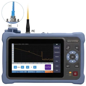
An OTDR trace is essentially a map of the fiber. A healthy fiber appears as a straight line sloping gently downward — that slope is the fiber’s attenuation. Features on the trace reveal specific events:
| What You See on the Trace | What It Means |
| Gentle downward slope | Normal fiber attenuation (loss per km) |
| Sharp spike, then the line continues lower | Reflective event — usually a connector |
| Sudden step down with no spike | Non-reflective event — typically a fusion splice or a bend |
| Large spike followed by a drop to noise | End of the fiber or a break |
From these features, the OTDR reports splice loss, connector loss, reflectance, total link loss, optical return loss (ORL), and the distance to every event — all from a single end of the fiber.
Key OTDR Terms: Dead Zone and Pulse Width
Two concepts come up constantly when people discuss OTDRs.
Dead Zone
A dead zone is the length of fiber right after a strong reflection where the OTDR cannot accurately detect or measure a second event. When a large reflection saturates the detector, the instrument needs a short recovery period before it can measure backscatter again. There are two kinds: the event dead zone (the minimum distance needed to distinguish two separate reflective events) and the attenuation dead zone (the minimum distance needed to measure loss after an event). Technicians often add a launch cable ahead of the link so the near-end dead zone falls outside the fiber under test.
Pulse Width
The pulse width sets a trade-off. A narrow pulse gives better spatial resolution and can separate closely spaced events, but it covers a shorter distance. A wide pulse carries more energy and reaches farther, but it blurs nearby events together. Choosing the right pulse width for the span under test is a core part of running a good measurement.
OTDR vs Optical Power Meter (OLTS)
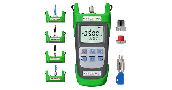
A common point of confusion is how an OTDR differs from an optical loss test set (OLTS), which pairs a light source and a power meter. They answer different questions.
| Aspect | OTDR | OLTS (Source + Power Meter) |
| What it measures | Distributed loss and the location of every event along the fiber | Total end-to-end insertion loss between two points |
| Ends required | Single-ended (test from one end) | Double-ended (source at one end, meter at the other) |
| Locates faults? | Yes — gives distance to each event | No — only a pass/fail total number |
| Typical role | Troubleshooting and detailed link characterization (Tier 2 / extended) | Certification of total loss (Tier 1) |
In standards such as ANSI/TIA-568, the OLTS is used for Tier 1 loss certification and the OTDR for Tier 2 troubleshooting and characterization. The two tools complement each other rather than replace each other.
Types of OTDR and Test Wavelengths
Not every OTDR is built for the same job, and understanding the categories helps you match the instrument to the network.
Bench-Top vs Handheld OTDRs
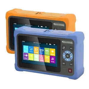
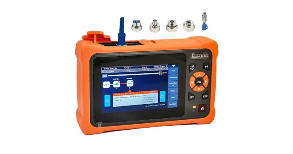
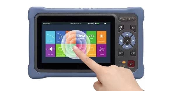
Bench-top OTDRs are larger, run on AC power, and offer highly specialized functions for laboratory characterization and research. Handheld OTDRs are smaller, lightweight, and battery-powered for use in the field. Field units vary widely in capability — some test only one fiber type or wavelength, while more capable models handle both single-mode and multimode fiber at multiple wavelengths and longer distances, covering a far broader range of applications.
Standard OTDR Wavelengths
OTDRs operate at wavelengths matched to the deployed network. The 1310 nm and 1550 nm windows are the dominant wavelengths for backbone and access-network testing on single-mode fiber. For in-service testing on live PON networks, longer wavelengths such as 1625 nm and 1650 nm are used because they fall outside the normal signal bands, allowing the fiber to be tested without interrupting service. Testing at more than one wavelength is useful because loss from bends and certain defects behaves differently at different wavelengths.
Intelligent Link Mapping
Modern OTDRs increasingly automate trace interpretation. Instead of asking the technician to read a raw single-pulse trace, intelligent link-mapping modes acquire multiple traces at several pulse widths and wavelengths, correlate the events across them, and present a single annotated link diagram with a pass or fail result for each event. This reduces the skill barrier and produces standardized, repeatable reports suitable for as-built documentation.
What Are OTDRs Used For?
- Fiber installation and acceptance: verifying that a newly installed link meets loss and reflectance targets.
- Fault location: pinpointing the distance to a break, bad splice, or damaged connector so a technician goes straight to the problem.
- Splice and connector evaluation: measuring the loss of each individual splice and connector along the run.
- Link documentation: producing a permanent trace and event map as an as-built record.
- PON and live-network testing: testing through splitters, often at 1625/1650 nm so the network stays in service.
Choosing the Right OTDR and Test Gear
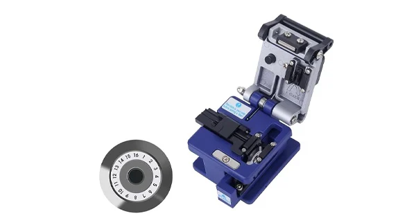
OTDRs range from large bench-top units for the lab to compact, battery-powered handhelds for the field, and they differ in wavelength coverage, dynamic range, and dead-zone performance. Aevumix supplies a complete range of optical communication test equipment — OTDRs, optical power meters, light sources, and inspection tools — for access, backbone, and data-center networks. If you would like help selecting the right instrument for your fiber type and test distances, get in touch with our team.
FAQs
What Is the Full Form of OTDR?
OTDR is the acronym for Optical Time-Domain Reflectometer, an instrument that characterizes an optical fiber by launching light pulses and analyzing the reflected and backscattered light that returns.
What Does an OTDR Actually Measure?
An OTDR measures fiber attenuation, splice loss, connector loss, reflectance, total optical return loss, and the distance to every event along the fiber — all from a single end of the link.
What Is the Difference Between an OTDR and a Power Meter?
A power meter (with a light source, as an OLTS) measures only the total insertion loss between two ends. An OTDR maps the entire fiber from one end, showing where each loss event is and how much loss it contributes, which is why it is used for troubleshooting and fault location.
What Is a Dead Zone on an OTDR?
A dead zone is the short length of fiber after a strong reflection where the OTDR cannot resolve or measure a second event, because the detector needs time to recover. Using a launch cable and an appropriate pulse width helps minimize its impact.
Why Is a Launch Cable Used With an OTDR?
A launch cable adds fiber length ahead of the link under test so the instrument’s near-end dead zone falls within the launch cable instead of the actual network. This lets the OTDR accurately measure the very first connector and events near the start of the link.