An OTDR trace looks simple at first — a line that slopes downward with a few spikes — but reading it well means understanding several concepts that trip up newcomers: pulse width, dead zones, launch cables, gainers, and how OTDR results differ from a power-meter measurement. This guide explains the OTDR trace and these key ideas so you can interpret results with confidence.
The Shape of a Trace
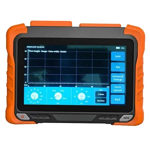
An OTDR trace plots returning light power (in dB) against distance along the fiber. A healthy fiber appears as a straight line sloping gently downward; that slope is the fiber’s attenuation. Events interrupt the line: a sharp spike is a reflective event such as a connector; a step down with no spike is a non-reflective event such as a splice or bend; and a large spike falling into noise marks the fiber end or a break.
What Does the Pulse Width Control on an OTDR Do?
The pulse width sets the length of each light pulse the OTDR launches, and it is a fundamental trade-off. A narrow pulse gives better spatial resolution — it can separate events that are close together and see fine detail — but it carries less energy and reaches a shorter distance. A wide pulse carries more energy and reaches much farther along a long span, but it blurs nearby events together. Choosing the right pulse width for the fiber under test is one of the most important settings: too narrow and you cannot reach the far end; too wide and you cannot resolve closely spaced connectors.
Understanding Dead Zones
After a strong reflection, there is a short stretch of fiber where the OTDR cannot accurately detect or measure a second event — the dead zone. When a large reflection saturates the detector, the instrument needs a brief recovery period. There are two kinds: the event dead zone (the minimum distance needed to distinguish two separate reflective events) and the attenuation dead zone (the minimum distance needed to measure loss after an event). A narrower pulse width reduces dead zones but shortens range, so again it is a compromise.
Why Use a Launch Cable in OTDR Testing?
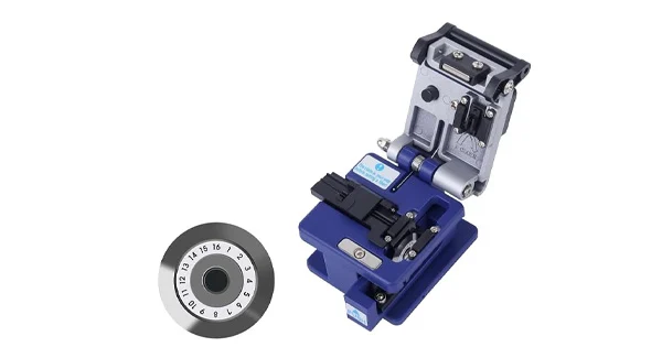
Because the OTDR’s own front-end reflection creates a near-end dead zone, the very first connector of your link can fall inside it and be impossible to measure. A launch cable (also called a launch or pulse-suppressor box) adds a length of fiber ahead of the link so that near-end dead zone falls within the launch cable rather than your network. This lets the OTDR accurately measure the first connector and the events near the start of the link. A matching receive (tail) cable does the same at the far end, allowing the last connector to be measured.
What Is a Gainer on an OTDR Trace?
A gainer is one of the most confusing features on a trace: a splice or connection that appears to add power, showing a step upward instead of down — effectively a negative loss. A passive splice cannot amplify light, so what is really happening?
The cause is a difference in the backscatter coefficient between the two fibers being joined, often due to mode-field-diameter mismatch (for example, where standard single-mode and bend-insensitive fibers meet). If the fiber on the far side scatters back more light than the fiber before it, the OTDR reads a higher level after the event than before and interprets it as a gain. The splice is not actually good or bad because of this — the reading is simply a measurement artifact from one direction.
How Gainers Are Corrected: Bidirectional Testing
Wherever there is a gainer in one direction, the same event measured from the opposite direction shows an exaggerated loss (a “loser”). The solution, required by industry standards such as TIA for documented splice loss, is bidirectional testing: measure the event from both ends and average the two results. For example, if one direction reads −0.08 dB (a gainer) and the other reads +0.22 dB, the true splice loss is their average, about 0.07 dB. Averaging cancels the backscatter artifact and leaves the real loss.
The Hidden Case: 0 dB Events
Backscatter differences do not only create gainers and exaggerated losses — sometimes they hide an event entirely. When two spliced fibers have moderately different characteristics, the increase in backscatter as light crosses the joint can almost exactly cancel the real loss at that point. The net backscatter level does not change, so from that direction the OTDR sees neither a loss nor a step and may not detect the event at all. This is another reason bidirectional testing matters: measuring from both ends and averaging reveals events that a single-direction trace would miss, and gives their true loss. If you rely on one direction only, a real splice can quietly vanish from your results.
Reading Splice Loss Correctly
Because of these effects, the loss a fusion splicer estimates and the loss an OTDR measures will rarely match exactly, and that is expected. The splicer’s figure comes from image analysis of the splice geometry and is useful for a quick go/no-go decision in the field. The OTDR measures real backscattered light and gives a truer value — but only when read correctly, which for documented splice loss means a bidirectional average rather than a single-direction number. There is no universal fixed limit for an individual splice; what ultimately matters is the total link loss measured against the link’s loss budget. Keeping this hierarchy in mind — total link loss first, individual events in context — prevents chasing artifacts that do not affect real performance.
OTDR vs OLTS: What Is the Difference?
A frequent question is how OTDR results differ from an optical loss test set (OLTS — a light source and power meter). They answer different questions.
| Aspect | OTDR | OLTS (Source + Meter) |
| What it measures | Distributed loss and the location of every event | Total end-to-end insertion loss |
| Ends required | Single-ended | Double-ended |
| Locates faults? | Yes — distance to each event | No — one total number |
| Standard role | Tier 2 troubleshooting / characterization | Tier 1 loss certification |
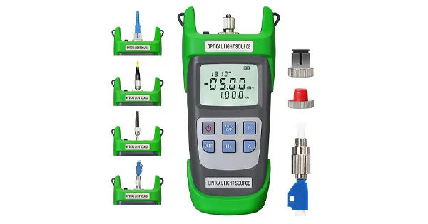
An OLTS gives the definitive end-to-end loss, including both end connectors, which is why standards use it for certification. An OTDR locates and characterizes each event. Because each has strengths, many technicians use both, plus a visual fault locator for quick checks.
Checking Your OTDR Is Accurate
To trust a trace, the instrument and setup must be sound. Keep the OTDR port inspected and clean, since a dirty port corrupts every trace. Use an appropriate launch cable, choose a pulse width suited to the span, and use enough averaging to lift real events out of the noise. Where accurate event loss matters and backscatter mismatch may exist, use bidirectional analysis rather than a single-direction reading. These practices are what separate a trustworthy result from a misleading one.
Get the Right OTDR Tools
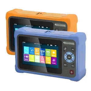
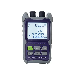
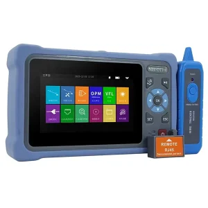
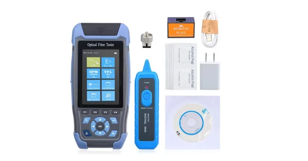
Accurate trace interpretation starts with the right instrument and accessories. Aevumix supplies handheld and bench OTDRs, launch and receive cables, optical power meters, light sources, and visual fault locators for every network type. If you would like help choosing OTDR equipment or launch cables for your fiber, contact our team.
FAQs
What Does Pulse Width Change on an OTDR?
Pulse width trades resolution for distance. A narrow pulse resolves closely spaced events and reduces dead zones but reaches a shorter distance; a wide pulse reaches farther on long spans but blurs nearby events together.
What Causes a Gainer on an OTDR Trace?
A gainer is caused by a difference in backscatter coefficient between two joined fibers, often from mode-field-diameter mismatch. The far fiber scatters more light back, so the OTDR reads an apparent gain. It is a measurement artifact, corrected by bidirectional averaging.
Why Is a Launch Cable Needed?
A launch cable moves the OTDR’s near-end dead zone out of the link under test, allowing the first connector and early events to be measured accurately. A receive cable does the same for the last connector at the far end.
What Is the Difference Between OTDR and OLTS?
An OLTS (source and power meter) measures total end-to-end insertion loss for Tier 1 certification. An OTDR maps the fiber from one end and locates each event for Tier 2 troubleshooting. They complement each other.
Why Test an OTDR in Both Directions?
Because backscatter differences between fibers make single-direction event losses inaccurate — sometimes showing gainers. Averaging measurements from both directions cancels the artifact and gives the true event loss, as standards require for documented splice loss.