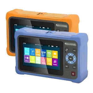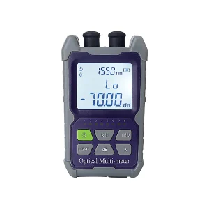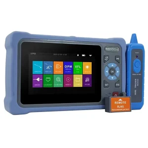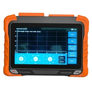
OTDR testing is one of the core methods for characterizing and troubleshooting fiber optic links. If you have seen the term on a test report or in a job description and wondered what OTDR testing is, what it measures, and how it works, this guide explains it clearly — from the meaning of the acronym to the physics behind the measurement.
What Does OTDR Mean?
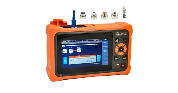
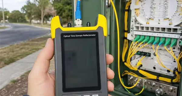
OTDR stands for Optical Time-Domain Reflectometer. The name describes the instrument precisely: it works with light (optical), it measures events by timing how long light takes to travel and return (time-domain), and it analyzes the reflected light coming back from the fiber (reflectometer). OTDR testing, then, is the process of using this instrument to map and characterize a fiber link.
What Is OTDR Testing?
OTDR testing is a single-ended measurement technique that builds a complete map of a fiber from just one end. The instrument injects short laser pulses into the fiber and measures the light that returns, then plots the result as a trace — a graph of returning light power against distance. From that single trace, OTDR testing reveals the location and characteristics of every connector, splice, bend, and break along the fiber, plus the fiber’s own attenuation.
This is what makes OTDR testing distinctive: unlike a simple loss measurement that gives one end-to-end number, OTDR testing tells you where each event is and how much it contributes.
How Does an OTDR Work?
An OTDR relies on two physical effects that send light back toward the instrument as a pulse travels down the fiber.
Rayleigh Backscatter
Microscopic variations in the glass continuously scatter a tiny fraction of the light in all directions. A small portion of this — Rayleigh backscatter — travels back toward the OTDR. Measuring this returning power along the fiber lets the instrument calculate attenuation over the whole length.
Fresnel Reflections
Where the refractive index changes abruptly — at connectors, splices, breaks, or the fiber end — a stronger reflection is produced. These Fresnel reflections appear as sharp spikes and let the OTDR pinpoint the exact location of each event.
From Time to Distance
The OTDR records how long each reflection takes to return. Since the speed of light in the fiber is known from its refractive index, that round-trip time converts directly into distance. The instrument fires many pulses and averages the returns to produce a clean, accurate trace.
What Does an OTDR Measure?
From a single trace, OTDR testing reports a rich set of results:
| Measurement | What It Tells You |
| Fiber attenuation | Loss per kilometer along the fiber |
| Splice loss | Loss at each fusion or mechanical splice |
| Connector loss | Loss at each connector or mating point |
| Reflectance | Strength of reflection at each event |
| Optical return loss (ORL) | Total reflected light for the whole link |
| Distance to event | Exact location of each connector, splice, or fault |
Reading an OTDR Trace
A trace is a map of the fiber. A healthy fiber shows a straight line sloping gently downward — that slope is the attenuation. Features on the line reveal events: a sharp spike is a reflective event such as a connector; a step down with no spike is a non-reflective event such as a splice or bend; and a large spike dropping into noise marks the fiber end or a break. Learning to read these shapes is the heart of interpreting OTDR testing.
The Strengths and Limits of OTDR Testing
OTDR testing is powerful, but knowing its boundaries prevents misreading results. Its great strength is location: from a single end it maps the whole fiber and gives the distance to every connector, splice, and fault, which is exactly what you need to send a technician straight to a problem. It also documents a link permanently as a trace. Its main limitation is that individual event losses can be distorted by differences between the two fibers at a joint, which is why accurate splice loss requires testing from both directions and averaging. It also has dead zones — short stretches after a strong reflection where a second event cannot be resolved — which is why launch cables are used. Understanding these limits is part of understanding what OTDR testing can and cannot tell you.
Setting Up an OTDR Test
A good OTDR test depends on a few setup choices as much as on the instrument. The connectors and the OTDR port must be inspected and cleaned first, because contamination corrupts the trace and can damage the port. A launch cable is connected ahead of the link so the first connector falls outside the near-end dead zone. Then the key parameters are set: the fiber type, the wavelength, the pulse width (a trade-off between resolution and distance), and the averaging time (longer averaging yields a cleaner trace on long links). Many modern OTDRs can set these automatically, but understanding them helps you get accurate results on difficult spans.
When OTDR Testing Is Used
- Installation and acceptance: confirming a new link meets loss and reflectance targets.
- Fault location: pinpointing the exact distance to a break, bad splice, or damaged connector.
- Splice and connector evaluation: measuring the loss of each individual event.
- Documentation: producing a permanent trace as an as-built record.
- Live PON testing: testing through splitters, often at 1625/1650 nm, without interrupting service.
Multimode and Single-Mode OTDR Testing
OTDR testing adapts to the fiber it examines. Single-mode links — the long-haul, access, and backbone fibers of telecom and CATV — are typically tested at 1310 and 1550 nm, with 1625 or 1650 nm reserved for testing live fibers because those wavelengths sit outside the active signal bands. Multimode links, common in data centers and building backbones, are tested at 850 and 1300 nm. Testing at more than one wavelength is valuable because bend-related loss shows up more strongly at longer wavelengths, so a fault that is invisible at one wavelength can appear clearly at another. Matching the OTDR’s wavelengths and fiber-type settings to the network under test is therefore a basic requirement for meaningful results, and it is why capable instruments cover several wavelengths in a single unit.
OTDR Testing vs Loss Testing
It is important to understand where OTDR testing fits. Under standards such as ANSI/TIA-568, an optical power meter and light source (OLTS) are used for Tier 1 insertion-loss certification — the definitive end-to-end loss number. OTDR testing is the Tier 2 method, used to characterize and locate individual events and troubleshoot problems. The two complement each other; OTDR testing does not replace loss certification, and loss certification cannot locate a fault.
Get the Right OTDR Equipment
OTDRs vary in wavelength coverage, dynamic range, and dead-zone performance, so matching the instrument to your network matters. Aevumix supplies handheld and bench OTDRs, launch cables, optical power meters, light sources, and visual fault locators for access, backbone, and data-center networks. If you would like help choosing OTDR equipment for your fiber type and distances, contact our team.
FAQs
What Does OTDR Stand For?
OTDR stands for Optical Time-Domain Reflectometer, an instrument that characterizes a fiber by launching light pulses and analyzing the reflected and backscattered light that returns.
What Is OTDR Testing Used For?
It is used to map a fiber from one end — measuring attenuation, splice and connector loss, reflectance, and the distance to every event — mainly for troubleshooting, fault location, acceptance, and documentation.
How Does an OTDR Work in Simple Terms?
It fires light pulses into the fiber and measures the light that scatters and reflects back. By timing those returns and knowing the speed of light in the fiber, it converts time into distance and builds a trace showing where each event is.
What Does an OTDR Actually Measure?
Fiber attenuation, splice loss, connector loss, reflectance, total optical return loss, and the distance to each event — all from a single end of the link.
Is OTDR Testing the Same as Loss Certification?
No. Loss certification (Tier 1) uses a power meter and light source for the end-to-end loss number. OTDR testing (Tier 2) locates and characterizes individual events. They are complementary methods.