An OTDR is the tool that shows you a complete map of a fiber link from a single end — every connector, splice, and fault, with the distance to each. Learning how to use an OTDR tester correctly, from setting parameters to using a launch cable, is what turns a confusing trace into an accurate diagnosis. This guide walks through the full workflow.
What an OTDR Tester Does
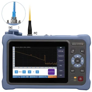
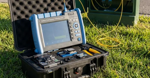
OTDR stands for Optical Time-Domain Reflectometer. It injects short laser pulses into a fiber and measures the light that returns — both Rayleigh backscatter along the fiber and stronger reflections at connectors, splices, and breaks. By timing those returns and converting time to distance, it builds a trace: a plot of returning light versus distance. From that single-ended measurement it reports splice loss, connector loss, reflectance, total loss, and the distance to every event.
Unlike a power meter and light source, which give total end-to-end loss, an OTDR tells you where each loss occurs — which is why it is the go-to tool for troubleshooting and detailed characterization.
What You Need Before Testing
- An OTDR matched to your fiber (single-mode and/or multimode) and wavelengths.
- A launch cable (also called a launch or pulse-suppressor box) to handle the near-end dead zone.
- A receive/tail cable if you want to measure the last connector.
- Cleaning and inspection tools for every connector.
How to Use an OTDR Tester: Step by Step
Step 1: Clean and Inspect the Connectors
Inspect and clean the OTDR port, the launch cable, and the fiber under test using the inspect–clean–inspect method. A dirty connector at the OTDR port corrupts every trace and can damage the port.
Step 2: Connect a Launch Cable
Connect a launch cable between the OTDR and the fiber under test. The launch cable adds fiber length ahead of the link so the instrument’s near-end dead zone falls within the launch cable, not your network. This lets the OTDR accurately measure the very first connector of the link.
Step 3: Set the Test Parameters
Select the fiber type, wavelength, and test limits for your application. Then set the key parameters: pulse width, range, and averaging time. A narrow pulse width gives better resolution to separate close events but reaches a shorter distance; a wide pulse reaches farther but blurs nearby events. Advanced OTDRs with auto-test can set these for you, but you can also set them manually for difficult spans.
Step 4: Run the Acquisition
Start the test. The OTDR fires pulses and averages many returns to build a clean trace. Longer averaging gives a smoother, higher-quality trace, especially on long links.
Step 5: Read the Trace
Interpret the result: a gentle downward slope is normal fiber attenuation; a sharp spike is a reflective event such as a connector; a step down with no spike is a non-reflective event such as a splice or bend; and a large spike dropping to noise is the fiber end. The OTDR lists each event with its loss, reflectance, and distance.
Reading OTDR Events
| Trace Feature | Event |
| Gentle downward slope | Normal fiber attenuation |
| Sharp spike | Reflective event — typically a connector |
| Step down, no spike | Non-reflective event — splice or bend |
| Large spike then noise | End of fiber or a break |
Key Settings Explained
Pulse Width
Pulse width is a trade-off between resolution and distance. Use a narrow pulse for short links or to separate closely spaced events; use a wider pulse to reach the far end of a long span.
Dead Zone and the Launch Cable
After a strong reflection, there is a short length where the OTDR cannot resolve a second event — the dead zone. A launch cable pushes the near-end dead zone out of your link so the first connector is measurable, and a receive cable does the same at the far end for the last connector.
Choosing Wavelengths and Using Auto Modes
An OTDR is normally run at the wavelengths the network uses — 1310 and 1550 nm for single-mode backbone and access work, with 1625 or 1650 nm reserved for testing live fibers because those wavelengths sit outside the active signal bands. Testing at more than one wavelength is valuable because bend-related loss shows up more strongly at longer wavelengths, so a fault invisible at 1310 nm may appear clearly at 1550 nm. Many modern OTDRs also offer an intelligent link-mapping or auto mode that acquires several traces at different pulse widths and wavelengths, correlates the events across them, and presents a single annotated diagram with a pass or fail per event. These modes reduce the skill needed to read a raw trace and produce standardized, repeatable reports.
Documenting and Comparing Traces
A trace is only as useful as the record you keep of it. Save each trace with the fiber identifier, wavelength, direction, and date, and store the results as an as-built record of the link. Good documentation does double duty: it certifies the installation now and gives you a baseline to compare against later, so when a link degrades you can see exactly which event changed. Where a specification requires it, run the OTDR bidirectionally and average the two directions, since some events read differently depending on which end you test from. Consistent, well-labeled records turn one-off measurements into a maintainable history of the network.
Common OTDR Mistakes to Avoid
- No launch cable: you cannot properly measure the first connector without one.
- Dirty OTDR port: corrupts every trace; always clean and inspect first.
- Wrong pulse width: too wide blurs events; too narrow won’t reach the end.
- Too little averaging: a noisy trace hides real events on long links.
- Reading loss from a single direction: some events need bidirectional testing for a true value.
OTDR With Other Fiber Tools
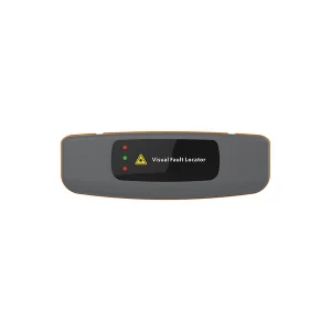
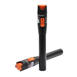
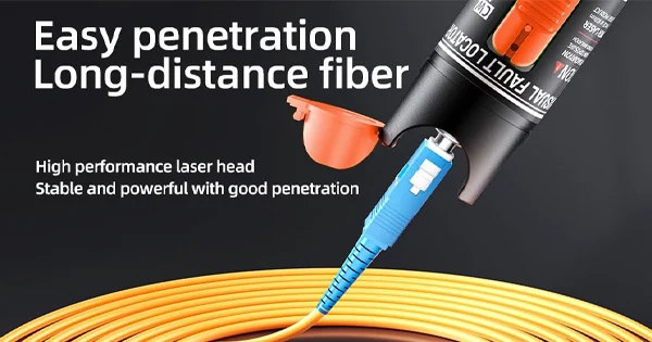
An OTDR excels at locating faults and characterizing a link, but standards use a power meter and light source (OLTS) for Tier 1 loss certification and the OTDR for Tier 2 troubleshooting. Many technicians carry both, plus a visual fault locator for quick checks. Together they cover verification, certification, and fault-finding.
Handheld vs Bench OTDRs
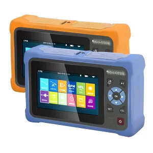
OTDRs come in two broad forms, and the right choice depends on where you work. Bench-top units are larger, run on mains power, and offer highly specialized functions for laboratory characterization and research. Handheld units are compact, battery-powered, and rugged for field use, which is what most installers and maintenance teams need day to day. Field OTDRs still vary widely: some test only one fiber type or a single wavelength, while more capable models handle both single-mode and multimode at several wavelengths and longer distances, and offer shorter dead zones for testing closely spaced connectors. Matching these capabilities to your fiber type, span lengths, and the density of connectors you test avoids both overspending on lab features you will not use and underspending on an instrument that cannot reach or resolve your links.
Get the Right OTDR
OTDRs vary in wavelength coverage, dynamic range, and dead-zone performance, so matching the instrument to your network matters. Aevumix supplies handheld and bench OTDRs, launch cables, optical power meters, light sources, and visual fault locators for access, backbone, and data-center networks. If you would like help choosing an OTDR for your fiber type and distances, contact our team.
FAQs
What Is an OTDR Tester Used For?
An OTDR characterizes a fiber from one end, reporting splice loss, connector loss, reflectance, total loss, and the distance to every event. It is mainly used for troubleshooting, fault location, and detailed link documentation.
Why Do I Need a Launch Cable?
A launch cable adds fiber ahead of the link so the OTDR’s near-end dead zone falls within it rather than your network, allowing accurate measurement of the first connector and events near the start of the link.
How Do I Choose the Pulse Width?
Use a narrow pulse for short links or to separate closely spaced events with better resolution, and a wider pulse to reach the far end of a long span. It is a trade-off between resolution and distance.
What Is a Dead Zone?
A dead zone is the short length after a strong reflection where the OTDR cannot resolve or measure a second event because the detector needs to recover. Launch and receive cables and an appropriate pulse width minimize its impact.
Is an OTDR the Same as a Power Meter Test?
No. A power meter and light source measure total end-to-end loss (Tier 1 certification). An OTDR maps the fiber from one end and locates each event (Tier 2). They complement each other rather than replace one another.