A fiber optic tester lets you confirm that a fiber link actually performs — not just that light passes through it. For most everyday work, “fiber optic tester” means an optical power meter paired with a light source, used to measure insertion loss. Learning how to use a fiber optic tester correctly, including the all-important reference step, is what separates an accurate result from a misleading one. This guide walks through the full process.
What a Fiber Optic Tester Measures
The core measurement is insertion loss (also called optical loss): the difference between the light launched into one end of a fiber and the light that arrives at the other end, expressed in decibels (dB). Insertion loss is the key factor in determining whether a fiber can support a given application. Industry standards specify the maximum allowed loss for each fiber type and application, so measuring it is how you certify a link.
The tester has two parts working together: a stabilized light source that launches a known optical power at a set wavelength, and an optical power meter that reads how much light arrives. The difference is the loss.
Power vs Loss: Two Different Measurements
It helps to distinguish the two things a fiber tester can tell you. Measuring optical power alone — connecting just the power meter to a live transmitter — shows the absolute signal level arriving in dBm, which is useful for confirming that equipment is emitting and that a signal has enough strength to reach the device at the far end. Measuring loss, by contrast, requires a light source as well: you launch a known power and compare it to what arrives, yielding the insertion loss in dB. Power tells you “is there enough light here?”; loss tells you “how much is this link taking away?” Certification is about loss, which is why a light source and power meter are used together as a set, but a power meter on its own remains handy for quick presence-of-signal checks during installation and restoration.
What You Need
- A stabilized light source (LED for multimode, laser for single-mode).
- An optical power meter with the right connector adapters (SC, FC, ST, LC).
- Known-good reference/launch cords of the correct fiber type.
- Cleaning and inspection tools for the connectors.
How to Use a Fiber Optic Tester: Step by Step
Step 1: Clean and Inspect Every Connector
This is the most important step. Dirt or dust on connectors significantly affects test results. Clean both ends of the reference and test fibers with the inspect–clean–inspect method before you connect anything.
Step 2: Power On and Match the Wavelength
Turn on the light source and power meter. Select the correct wavelength for your application — 850/1300 nm for multimode, 1310/1550 nm for single-mode — and make sure the source and meter are set to the same wavelength. A mismatch produces a wrong loss value.
Step 3: Set the Reference (Zeroing)
Connect the light source directly to the power meter with a single reference cord, with no extra adapters between them. Press the meter’s reference (REF) button to store that power level as 0 dB. This excludes the reference cord’s own loss from your results. Skipping this step makes results inaccurate and pessimistic — a good link can wrongly fail.
Step 4: Connect the Link Under Test
Without changing the source, connect the source to the transmitting end of the link and the power meter to the receiving end. Keep the fiber free of sharp bends, twists, or stress.
Step 5: Read and Record the Loss
The meter now displays the loss relative to your reference, in dB. Record the loss, the reference level, and the wavelength. Repeat at each required wavelength and, where specified, in both directions. Compare the result against the allowed loss budget to pass or fail the link.
Interpreting Your Results
| Reading | What It Suggests | Next Step |
| Loss within the budget | Link passes for the application | Record and certify |
| Loss slightly high | Dirty or marginal connectors | Re-clean, inspect, re-test |
| Loss much too high | Bad splice, damaged fiber, or bad mating | Inspect connectors; run an OTDR to locate |
| No reading at all | Break, wrong wavelength, or bad connection | Check continuity with a VFL; verify settings |
Common Mistakes to Avoid
- Skipping the reference step: the single biggest cause of misleading results.
- Mismatched wavelengths: source and meter must be set the same.
- Dirty connectors: always clean and inspect before testing.
- Not letting the source stabilize: a drifting output corrupts the reading.
- Stressing the fiber: bends and twists add loss that is not really in the link.
Wavelengths, Directions, and Documentation
Thorough loss testing is about more than a single reading. Because fiber attenuation varies with wavelength, links are usually tested at each wavelength the network uses — 850 and 1300 nm for multimode, 1310 and 1550 nm for single-mode — since a link can pass at one wavelength and reveal a bend-related loss at another. Many specifications also call for bidirectional testing, measuring the link from both ends and averaging, because a single direction can under- or over-state the loss at certain events. Finally, record every result: the loss, the reference power, the wavelength, the direction, and the date. Organized test records let you certify the install now and spot performance degradation or aging when you compare against them later.
Reference Methods Matter
How you set the reference affects what your result includes. A one-cord (one-jumper) reference, where the source and meter are joined by a single launch cord before zeroing, includes the loss of the connectors at both ends of the link in your measurement — the most complete and common approach for certifying a link end to end. Some specifications call for two- or three-cord references instead, which change which connectors are counted. The key point is consistency: use the reference method your standard or customer requires, keep your reference cords clean and known-good, and note which method you used alongside the results so the numbers can be interpreted correctly.
When to Add an OTDR
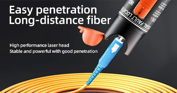
A power meter and light source give you unambiguous end-to-end loss, including the connectors at each end — ideal for Tier 1 certification. But they cannot tell you where a problem is. When loss is too high and you need to locate the fault, an OTDR maps the fiber and reports the distance to each event. Many technicians pair the two, plus a visual fault locator for quick checks.
Troubleshooting High Loss Readings
When a link measures more loss than its budget allows, work through the causes in order of likelihood before condemning the fiber. Dirty connectors are by far the most common culprit, so re-clean and inspect both ends with the inspect–clean–inspect method and re-test. Confirm the source and meter are set to the same wavelength and that the source has stabilized. Check that the fiber is not sharply bent, twisted, or stressed anywhere along the run, since a tight bend adds real loss. Verify the reference was set correctly with a known-good cord. If loss is still high after all of that, the problem is likely a poor splice, a damaged section, or a bad mating deeper in the link — and locating it precisely is exactly the job an OTDR is built for.
Get the Right Fiber Testers
Accurate testing depends on quality, well-matched instruments. Aevumix supplies stabilized light sources, optical power meters, OLTS kits, OTDRs, and visual fault locators for multimode and single-mode networks. If you would like help choosing a fiber tester for your work, contact our team and we will match the right tools to your needs.
FAQs
What Is a Fiber Optic Tester Used For?
Most commonly, to measure insertion (optical) loss — the difference between light launched and light received, in dB. This determines whether a fiber link meets its loss budget and can support a given application.
Why Do I Need to Set a Reference First?
Referencing zeroes the meter to the light source through a known-good cord so that cord’s loss is excluded. Without it, results are inaccurate and pessimistic, and a good link may wrongly fail.
Do the Source and Meter Need the Same Wavelength?
Yes. The optical power meter must be set to the same wavelength the light source is emitting, or the loss value will be wrong. Many modern testers synchronize wavelength automatically.
What If the Loss Is Too High?
Re-clean and inspect the connectors and re-test first, since contamination is the most common cause. If loss remains high, the fault may be a bad splice, damaged fiber, or poor mating — use an OTDR to locate it.
Can a Fiber Optic Tester Find Where a Fault Is?
A power meter and light source measure total loss but not location. To find the distance to a fault, use an OTDR, and use a visual fault locator for quick visual checks of breaks and bad joints.