An OTDR is the most powerful diagnostic tool in fiber optics, and understanding how an OTDR works makes its traces far easier to read. This guide focuses on the working principle — the physics of Rayleigh scattering and Fresnel reflection that lets a single instrument map an entire fiber link from one end. (For a broader introduction to OTDR testing and terminology, see our guides on what OTDR testing is and what OTDR stands for.)
What Is an Optical Time-Domain Reflectometer?
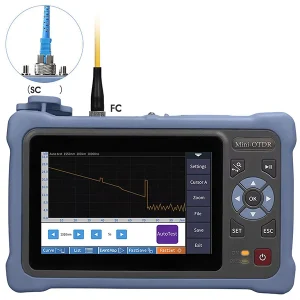
An Optical Time-Domain Reflectometer (OTDR) is an instrument for the non-destructive testing of optical fibers. From a single end of the fiber, it can measure overall loss, locate and quantify the loss of individual splices and connectors, find breaks, and measure distances — presenting all of it as a graphical trace. It does this without needing access to the far end, which is what makes it so valuable for characterizing and troubleshooting real links.
The Core Working Principle
The OTDR works on a radar-like principle. It sends a short, high-power laser pulse into the fiber and measures the light that returns over time. A laser diode generates the pulse; a directional coupler routes returning light to a sensitive photodiode; and the instrument records the returning optical power as a function of time. Because light travels through fiber at a known speed, the round-trip time of any returning light translates directly into a distance — so every feature the OTDR detects can be placed at a precise location along the fiber.
Two distinct physical phenomena send light back to the OTDR: Rayleigh scattering and Fresnel reflection.
Rayleigh Scattering: Measuring Continuous Loss
As the pulse travels down the fiber, microscopic fluctuations in the glass scatter a tiny fraction of the light in all directions — this is Rayleigh scattering. A small portion scatters directly backward toward the OTDR, creating a continuous, weak return signal all along the fiber. The predictable nature of Rayleigh scattering is the foundation of OTDR measurement: the amount of backscattered light reaching the detector indicates the attenuation of the fiber at each point. On the trace, this appears as a gently downward-sloping line — the backscatter weakening with distance because of the fiber’s loss. The slope of that line is the fiber’s attenuation in dB/km.
Fresnel Reflection: Locating Events
The second phenomenon is Fresnel reflection, which occurs wherever the light meets a boundary between two materials of different refractive index — such as a connector, a mechanical splice, or the glass-to-air interface at a break or the fiber’s end. At these points, a larger, discrete amount of light reflects straight back, appearing on the trace as a sharp spike. Fresnel reflections let the OTDR pinpoint connectors, breaks, and the fiber end. The strength of the reflection also indicates reflectance — useful for judging connector quality and return loss.
How the Trace Is Built
By combining these two effects over the pulse’s round trip, the OTDR assembles the trace:
| Trace Feature | Cause | Meaning |
| Gentle downward slope | Rayleigh backscatter | Fiber attenuation (dB/km) |
| Sharp spike | Fresnel reflection | Connector, mechanical splice, or end |
| Sudden step down | Localized loss | Splice or bend (little/no reflection) |
| Spike then signal ends | Strong Fresnel + no more backscatter | Fiber break or the fiber end |
Loss of a splice or connector is calculated from the drop in backscatter level across the event; distance comes from the timing of the return.
Why Loss Is Measured “Indirectly”
A key subtlety of the OTDR principle is that it measures loss indirectly, by analyzing backscatter and reflection rather than by comparing power at two ends the way an optical power meter does. This single-ended, indirect approach is the OTDR’s great strength — it needs access to only one end and reveals the loss of every point along the link — but it also means the trace is an interpretation of returning light, which is why understanding the underlying physics matters when reading results.
Pulse Width and the Trade-Offs It Creates
The width of the launched pulse is central to the working principle and involves a trade-off. A longer pulse injects more energy, producing stronger backscatter that reaches farther down long fibers — but it lengthens the “dead zone,” the minimum distance needed to resolve two separate events, so closely spaced features blur together. A shorter pulse gives finer resolution and a shorter dead zone but does not travel as far. This is why OTDRs let you choose pulse width, and why long-haul and short-link testing use different settings.
Why Bidirectional OTDR Testing Is Used
A subtle consequence of the OTDR’s backscatter principle is that a single-ended measurement can misjudge individual events. Because the OTDR infers splice and connector loss from the change in backscatter level across the event, and because two fibers joined at that point can have slightly different backscatter characteristics, an event can read as more or less lossy than it truly is depending on which end you test from — occasionally even appearing as an apparent “gain,” which is physically impossible for a passive joint. Testing from both ends and averaging the two results cancels this artifact and yields the true loss of each event. This is why careful characterization of a link is done bidirectionally, and why the OTDR’s indirect, backscatter-based principle — powerful as it is for single-ended mapping — is complemented by measuring in both directions when accurate per-event loss is required.
The Dead Zone
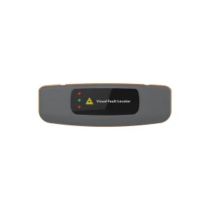
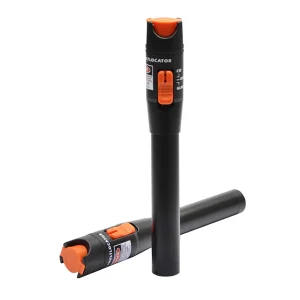
Because a strong reflection momentarily saturates the detector, there is a region right after each reflective event — and especially at the front connector — where the OTDR cannot resolve detail. This near-end “dead zone” is an inherent consequence of the reflection-based principle, and it is exactly why a visual fault locator is used alongside an OTDR to catch faults close to the connector that the OTDR cannot see.
Wavelength and the Working Principle
Wavelength plays a role in the OTDR principle worth noting. Rayleigh scattering depends on wavelength — it is stronger at shorter wavelengths and weaker at longer ones — which is one reason 1550 nm, with its low attenuation, is favored for long-distance links and long-range OTDR testing. Because the backscatter level and the fiber’s loss both vary with wavelength, an OTDR is often used at the same wavelength the network operates on, so the measured loss reflects real operating conditions. Testing at multiple wavelengths can also reveal certain faults: a macrobend, for instance, causes more loss at longer wavelengths, so a larger loss at 1550 nm than at 1310 nm at the same point is a classic signature of a bend rather than a connector or splice. Understanding that the OTDR’s backscatter-and-reflection principle is wavelength-dependent helps explain why technicians choose test wavelengths deliberately rather than arbitrarily.
Get the Right OTDR and Fiber Test Tools
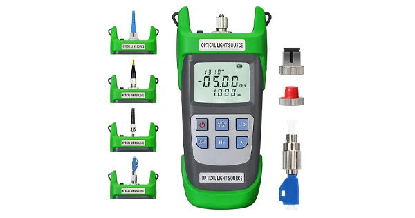
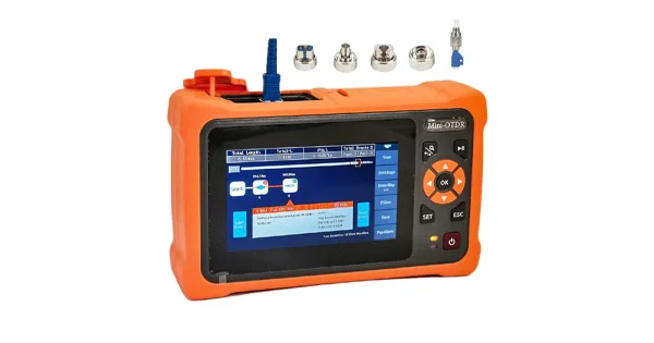
Understanding the principle helps you choose and use the right instrument. Aevumix supplies OTDRs, optical power meters, light sources, and visual fault locators for single-mode and multimode networks, along with inspection and cleaning tools. If you would like help choosing an OTDR for your fiber and distances, contact our team.
FAQs
What Is the Working Principle of an OTDR?
An OTDR sends a laser pulse into the fiber and measures the light returning over time. Rayleigh scattering gives a continuous backscatter that reveals attenuation, while Fresnel reflection produces spikes that locate connectors, splices, breaks, and the fiber end. Round-trip time converts to distance.
What Is the Difference Between Rayleigh Scattering and Fresnel Reflection?
Rayleigh scattering is a continuous, weak backscatter from microscopic fluctuations in the glass, indicating fiber loss. Fresnel reflection is a larger, discrete reflection at refractive-index boundaries like connectors and breaks, appearing as sharp spikes.
How Does an OTDR Measure Distance?
Light travels through fiber at a known speed, so the OTDR converts the round-trip time of returning light into distance. This lets it place every event — splice, connector, or break — at a precise location along the fiber.
Why Does an OTDR Have a Dead Zone?
A strong reflection briefly saturates the detector, creating a region right after each reflective event where detail cannot be resolved — especially at the front connector. This is why a VFL is used to find near-end faults the OTDR misses.
Does an OTDR Measure Loss Directly?
No. Unlike an optical power meter, an OTDR measures loss indirectly by analyzing backscatter and reflection from a single end. This reveals the loss of every point along the link but makes the trace an interpretation of returning light.