At some point every fiber technician needs to join two fibers together — to extend a run, repair a break, or connect equipment. But how do you connect fiber optic cable to fiber optic cable? There are three main methods, each suited to different situations. This guide explains fusion splicing, mechanical splicing, and connectors, with the steps and trade-offs of each.
Three Ways to Join Fiber
Unlike copper, you cannot simply twist two fibers together. Joining fiber means aligning two hair-thin glass cores precisely so light passes across the junction with minimal loss. The three standard methods are:
- Fusion splicing — permanently fusing two fibers with an electric arc.
- Mechanical splicing — aligning and holding two fibers in a precision fixture.
- Connectors — terminating each fiber with a connector and mating them through an adapter.
Method 1: Fusion Splicing
Fusion splicing is the industry standard for permanent, low-loss joins. A fusion splicer aligns the two prepared fiber ends and fuses them together with an electric arc, creating a continuous glass path. It delivers the lowest loss and reflection of any method, which is why it is used for FTTx, backbone links, buried splice closures, and data-center panels.
Fusion Splicing Steps
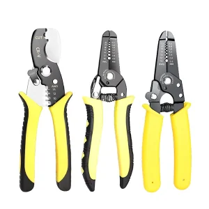
- Strip the coating from both fibers to bare glass.
- Clean the bare fibers with a lint-free wipe and fiber-grade fluid.
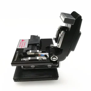
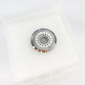
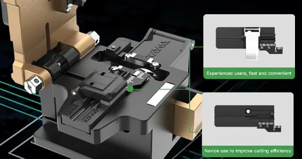
- Cleave each fiber with a precision cleaver for a flat, perpendicular end face.
- Place the fibers in the splicer, which aligns them and fuses them with an arc.
- Protect the joint with a heat-shrink splice protection sleeve.
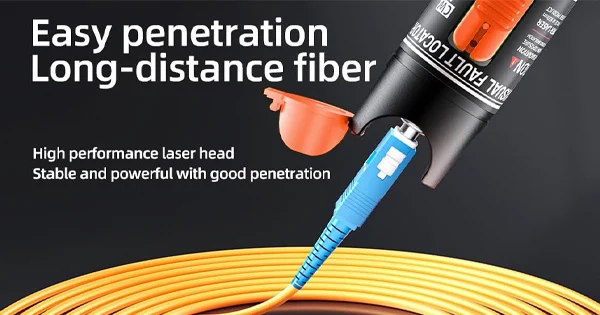
- Test the splice with a VFL or OTDR.
Fusion splicing needs more equipment and skill, but produces the strongest, lowest-loss joints.
Method 2: Mechanical Splicing
Mechanical splicing aligns two cleaved fibers inside a small precision fixture that holds them end to end, often using an index-matching gel to reduce reflection at the junction. It is faster and needs less equipment than fusion splicing — no splicer required — but generally results in higher loss and reflection. That makes it well suited to quick repairs, temporary fixes, and situations where a fusion splicer is not available.
Mechanical Splicing Steps
- Strip, clean, and cleave both fibers, just as for fusion splicing (a cleaver with an angle below about 3° is used).
- Insert the fibers into the mechanical splice fixture from each side until they meet.
- Secure the fixture to clamp the fibers in alignment.
- Test the join.
Method 3: Connectors
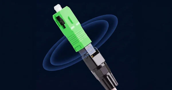
The third approach is to terminate each fiber with a connector (such as SC, LC, or FC) and join them through a mating adapter or at a patch panel. This is the most flexible method because the connection can be unplugged and reconnected easily, which is ideal for equipment ports, patch panels, and anywhere links change. Connectors can be added by fusion splicing a pre-polished “splice-on” connector, by field-installable mechanical connectors, or by using factory-terminated patch cords and pigtails. The trade-off is that a mated connector pair typically has slightly higher loss than a fusion splice and must be kept clean.
Comparing the Three Methods
| Method | Loss | Reconnectable? | Best For |
| Fusion splicing | Lowest | No (permanent) | Backbone, FTTx, permanent low-loss joins |
| Mechanical splicing | Higher | Semi-permanent | Quick repairs, temporary fixes, no splicer |
| Connectors | Moderate | Yes | Equipment ports, patch panels, changeable links |
Choosing the Right Method for the Job
Picking among the three methods comes down to a few practical questions. How important is loss? For backbone spans, long-haul links, and anything where every fraction of a decibel counts, fusion splicing is the clear choice. Is the join permanent or will it change? Equipment ports and patch panels that get reconfigured call for connectors, while a permanent buried joint suits a splice. What equipment do you have on hand? A fusion splicer is a significant investment, so field repairs without one often use a mechanical splice. And how quickly is it needed? Mechanical splices and field connectors are fast, while fusion splicing takes a little longer but rewards you with the best performance. In many real networks all three appear together — fusion splices in the backbone, connectors at the panels and equipment, and the occasional mechanical splice for an emergency repair — so understanding the trade-offs lets you apply the right one in each place.
What Every Method Has in Common
Whichever method you choose, three preparation steps are universal: strip, clean, and cleave. Every good join starts with correctly stripped fiber, thoroughly cleaned bare glass, and a precise cleave. Cleanliness is critical throughout — contamination on an end face or in a connector is the number-one cause of loss and reflection — so inspect and clean before mating connectors, and clean bare fiber before cleaving. Skimping on preparation is the most common reason a join fails, regardless of method.
Protecting and Documenting the Join
Finishing a join properly is what makes it last. A fusion splice is fragile bare glass at the joint until it is protected, so a heat-shrink splice protection sleeve with an internal strength member is applied and heated to reinforce it against bending and to guard against moisture. Mechanical splices and connectors have their own housings that provide this protection. Once protected, the join is secured in a splice tray, closure, or patch panel where it is supported and strain-relieved rather than left to hang on the fiber. It is also good practice to test and document each join — recording the measured loss with a power meter or an OTDR trace — so you have an as-built record for acceptance and a baseline to compare against if the link degrades later. A join that is well protected, properly housed, and documented is far more reliable over its life than one simply made and left exposed.
Safety When Joining Fiber
Joining fiber involves bare glass and cleaved offcuts, so wear safety glasses, collect every shard in a sharps container, and never look into a fiber that may carry light — the wavelengths used are invisible and can harm your eyes. Treat every fiber as potentially live and use a VFL or scope rather than your eye to check it.
Why Cleanliness Decides the Outcome
If there is one factor that separates a good join from a bad one across all three methods, it is cleanliness. Contamination on a connector end face or a speck of debris on a bare fiber before splicing is the single most common cause of loss and reflection, and it is entirely preventable. For connectors, that means following the inspect–clean–inspect routine every time before mating, using proper lint-free wipes, fiber-grade fluid, and a scope rather than guessing. For splices, it means cleaning the bare fiber before cleaving and never touching the cleaved end face. Even the finest fusion splicer and the most precise cleaver cannot compensate for a dirty end face — the contamination ends up embedded in the join. Treating cleanliness as a non-negotiable discipline, rather than an occasional extra, is what makes the difference between a link that quietly performs for years and one that suffers mysterious, intermittent loss.
Get the Right Tools for Joining Fiber
The right method depends on your loss requirements and equipment, but every method needs quality preparation tools. Aevumix supplies fusion-splicing accessories, fiber cleavers, strippers, mechanical splices, connectors, cleaning and inspection tools, and test equipment like VFLs and OTDRs. If you would like help choosing the right approach and tools for joining your fiber, contact our team.
FAQs
How Do You Connect Two Fiber Optic Cables Together?
By fusion splicing (fusing the fibers with an arc for the lowest loss), mechanical splicing (aligning them in a fixture for a faster, higher-loss join), or connectors (terminating each end and mating them through an adapter for a reconnectable link). All three start with strip, clean, and cleave.
Which Method Has the Lowest Loss?
Fusion splicing has the lowest loss and reflection, which is why it is used for permanent backbone and FTTx joins. Mechanical splices and connectors have somewhat higher loss.
When Should I Use a Mechanical Splice Instead of Fusion?
Use a mechanical splice for quick repairs, temporary fixes, or when a fusion splicer is not available. It is faster and needs less equipment, at the cost of higher loss and reflection.
Can I Reconnect a Fiber Join Later?
Connectors are designed to be unplugged and reconnected, making them ideal for changeable links and equipment ports. Fusion splices are permanent, and mechanical splices are semi-permanent.
Do All Methods Require Cleaving?
Yes. Fusion and mechanical splices and splice-on connectors all need the fiber stripped, cleaned, and cleaved to a flat end face first. Cleave quality strongly affects the loss of the finished join.