The phrase “make a fiber optic light source” can mean two very different things. For a hobby craft, it means feeding light into decorative plastic fibers. But in networking and telecom, it means setting up a proper optical light source to launch a known signal into a fiber for testing. This guide focuses on the professional version: how a fiber optic light source is built, how to set one up correctly, and how to use it to test a fiber link.
First, What a Fiber Optic Light Source Actually Is
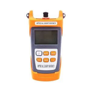
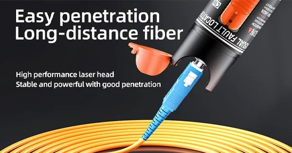
A fiber optic light source generates a stable optical output at one or more specific wavelengths and couples that light into a fiber. In testing, it launches a known power so a technician can measure how a fiber and its connectors perform. The two building blocks of any source are the emitter (an LED or a laser diode) and the coupling and stabilization that deliver a steady output into a connectorized port.
The Core Components of a Light Source
Understanding what goes into a source explains why a purpose-built instrument beats an improvised one.
- Emitter: an LED for multimode work (850 nm, 1300 nm) or a laser diode — Fabry-Perot or DFB — for single-mode work (1310 nm, 1550 nm, sometimes 1625 nm).
- Optical isolator: built in to protect the emitter from back reflections and keep the output stable.
- Stabilization circuit: holds the output power steady over time and temperature so measurements stay repeatable.
- Modulation control: provides continuous-wave (CW) output plus tones such as 270 Hz, 1 kHz, and 2 kHz for fiber identification.
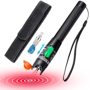
- Connector interface: an interchangeable adapter (SC, FC, ST, LC) that couples the light cleanly into the fiber under test.
The reason home-made light will not work for real testing is that these elements — stability, correct wavelength, clean coupling — are exactly what make a measurement trustworthy.
How to Set Up a Fiber Optic Light Source for Testing
Once you have a proper source, setting it up correctly is straightforward. Follow these steps.
Step 1: Match the Source to the Fiber
Confirm your fiber type. Use an LED source at 850/1300 nm for multimode, or a laser source at 1310/1550 nm for single-mode. Using the wrong emitter type for the fiber produces measurement errors.
Step 2: Fit the Right Adapter and Clean the Connectors
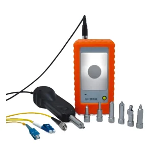
Attach the correct adapter (SC, FC, ST, or LC) for your patch cord, then inspect and clean both the source port connector and the test cord using the inspect–clean–inspect method. A dirty connector at the launch point contaminates every reading.
Step 3: Power On and Let It Stabilize
Turn on the source and select the wavelength. Allow it to stabilize before taking any measurement — skipping this step is a common mistake, because early output fluctuation leads to inaccurate results.
Step 4: Select the Output Mode
Choose continuous wave (CW) for a steady output when measuring loss, or a modulation tone (270 Hz, 1 kHz, or 2 kHz) when you need a compatible power meter or fiber identifier to recognize the wavelength and confirm the fiber.
Step 5: Connect and Measure With a Power Meter
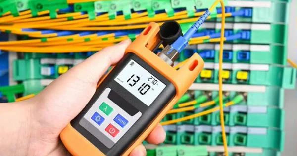
Connect the source to one end of the link and an optical power meter to the other. Set the meter to the same wavelength. The source launches a known power, the meter reads what arrives, and the difference is the end-to-end insertion loss. Together they form an Optical Loss Test Set (OLTS).
Setting the Reference (Zeroing)
For an accurate loss result, set a reference first. Connect the source to the power meter using a known-good launch cord, then zero (reference) the meter to that power level so the launch cord’s own loss is excluded. Only then insert the link under test. Skipping the reference step is one of the most common causes of misleading loss numbers.
Common Setup Mistakes to Avoid
| Mistake | Result | Fix |
| Not stabilizing before measuring | Output fluctuation, inaccurate loss | Let the source warm up and settle first |
| Using the wrong fiber/emitter type | Measurement errors | LED for multimode, laser for single-mode |
| Dirty launch connector | Corrupted readings on every test | Inspect and clean before connecting |
| Skipping the reference step | Launch-cord loss counted in the result | Reference the meter before inserting the link |
| Mismatched wavelength on the meter | Wrong loss value | Set source and meter to the same wavelength |
Why a Home-Made Source Won’t Pass Real Tests
It is worth being clear about the limits of improvisation. You can shine a flashlight or an LED into a bundle of decorative plastic fiber and get a pretty glow, and for a craft that is fine. But that light has no defined wavelength, no stabilized output, and no calibrated power level — the three things a measurement depends on. Without a known launch power you cannot calculate loss, and without a stable, single-wavelength output the power meter has nothing meaningful to read. This is the practical reason technicians buy purpose-built sources: the value is not the light itself but the accuracy and repeatability engineered around it. If your goal is decoration, improvise freely; if your goal is to test a fiber, you need a real instrument.
Source vs Transmitter: Clearing Up the Confusion
People sometimes conflate a test light source with the transmitter inside network equipment. Both launch light into a fiber, but their jobs differ. A network transmitter carries actual data, modulating the light at high speed to encode information. A test light source, by contrast, launches a clean, stable, known optical power at a set wavelength — it is not carrying data, it is providing a reference the power meter can measure against. That is why a test source emphasizes stability and calibration over speed: its whole purpose is to produce a predictable output so the loss reading reflects the fiber, not the equipment. When you “make” or set up a light source for testing, you are building this reference tool, not a data transmitter.
Understanding Wavelengths in Your Setup
Choosing the wavelength is not arbitrary — it must match the fiber and the network. Multimode fiber is tested at 850 nm and 1300 nm, the windows where multimode links operate. Single-mode fiber is tested at 1310 nm and 1550 nm, the two dominant telecom wavelengths, because attenuation and behavior differ between them. A link can look fine at one wavelength and reveal a bend-related loss at another, which is why testing at more than one wavelength gives a fuller picture. For in-service testing on live networks, 1625 nm and 1650 nm are used because they sit outside the active signal bands and let you test without interrupting traffic. Whatever you select on the source, set the power meter to the identical wavelength or the loss value will be wrong.
Laser Safety When Using a Light Source
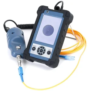
A fiber light source emits invisible optical energy, so handle it with basic laser-safety discipline. Never look directly into a source port, an emitting connector, or the end of a fiber that may be carrying light — the wavelengths used are invisible and can be harmful to your eyes. Keep unused ports capped, treat every fiber as if it may be live, and switch the source off before disconnecting. When inspecting connectors, use a fiber scope or video probe rather than your eye. These habits cost nothing and protect your vision throughout a testing session.
Get a Proper Light Source From Aevumix
For reliable fiber testing you need a purpose-built, stabilized light source — not an improvised one. Aevumix supplies stabilized LED and laser light sources, optical power meters, and complete OLTS kits for both multimode and single-mode networks, with the adapters and wavelengths your work requires. If you would like help choosing and setting up the right light source, contact our team.
FAQs
Can I Make a Fiber Optic Light Source at Home?
You can feed light into decorative plastic fiber for a craft, but you cannot make a source suitable for fiber testing at home. Test sources need a stabilized emitter, the correct wavelength, an optical isolator, and clean coupling — the very things that make a measurement accurate.
What Do I Need to Test a Fiber With a Light Source?
You need a light source matched to your fiber (LED for multimode, laser for single-mode), an optical power meter set to the same wavelength, clean patch cords, and the correct adapters. The source and meter together form an OLTS that measures insertion loss.
Why Should I Let the Light Source Stabilize?
A source that has not settled produces fluctuating output, which corrupts the reading on the power meter. Letting it stabilize ensures the loss measurement reflects the true performance of the link rather than equipment drift.
What Is the Reference (Zeroing) Step For?
Referencing sets the meter’s baseline using a known-good launch cord so that cord’s own loss is excluded from the result. Without it, you count extra loss that does not belong to the link under test.
What Wavelength Should I Set the Source To?
Match it to your network: 850/1300 nm for multimode, 1310/1550 nm for single-mode, and 1625 nm for testing outside the active signal band. Always set the power meter to the same wavelength you selected on the source.