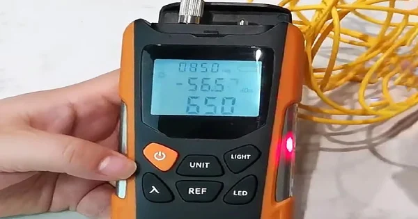
When you look at an optical power meter, the number on screen can mean very different things depending on the units and how the meter was set up. Understanding optical power meter readings — what dBm and dB mean, what a “good” value looks like, and how optical power measurement actually works — is essential for anyone testing fiber. This guide explains it clearly.
What Is Optical Power Measurement?
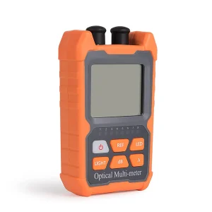
Optical power measurement is the process of quantifying how much light energy is present in a fiber at a given point. An optical power meter does this by collecting the light arriving on a photodetector and converting it into a power reading. It is the foundation of fiber testing: from this single measurement you can confirm equipment is transmitting, check that enough signal reaches the far end, and — with a light source — calculate a link’s loss.
Reading the Meter: dBm vs dB
The most important thing to understand about a power meter reading is which of two units you are looking at.
dBm — Absolute Power
A reading in dBm is an absolute measure of optical power — how much light is actually present, referenced to one milliwatt. It answers “how strong is this signal?” A live signal from network equipment or a light source is read in dBm. More negative numbers mean less power: for example, −6 dBm is a stronger signal than −20 dBm.
dB — Relative Loss
A reading in dB is a relative measure — how much power has been lost compared to a reference level you set beforehand. It answers “how much is this link taking away?” After you reference the meter to a source, the display shows the link’s insertion loss directly in dB.
The key relationship: dBm tells you the power that is there; dB tells you the difference from a baseline. The reference step is what converts an absolute reading into a loss reading.
Reading Types at a Glance
| Unit | Measures | Answers | Typical Use |
| dBm | Absolute optical power | How much light is present? | Checking a live signal or source output |
| dB | Loss relative to a reference | How much is being lost? | Measuring link insertion loss |
What Is a “Good” Power Reading?
There is no single universal number — it depends on the network and the equipment. What matters is whether the received power is strong enough for the device at the far end to operate reliably, and whether a link’s loss falls within its loss budget. Every optical system has a specified range: too little power and the receiver cannot recover the signal; sometimes too much power can overload it. The correct approach is always to compare your reading against the specification for that link or device, not against a generic “good” value.
How Optical Power Measurement Works
Inside the meter, a photodiode converts incoming light into an electrical current proportional to the optical power, which the instrument then displays as a calibrated reading. Because a photodiode’s response varies with wavelength, the meter must be told which wavelength it is measuring — setting the wrong wavelength gives a wrong value. That is why you always select the correct wavelength (for example 1310 or 1550 nm) before reading, and why, when measuring loss, the meter and the light source must be set to the same wavelength.
When You Measure Optical Power
Optical power measurement comes up throughout the life of a fiber link. During installation and restoration, a quick absolute-power reading confirms that a transmitter is emitting and that the received level is high enough for the equipment at the far end. During acceptance testing, a referenced loss reading certifies that a link meets its budget before it goes into service. During troubleshooting, comparing the measured power or loss against the expected value narrows down whether the problem is a dirty connector, a bad splice, or a break. And during ongoing maintenance, periodic readings compared against earlier records reveal gradual degradation — a slowly rising loss — before it becomes an outage. The same simple measurement supports every one of these stages, which is why the power meter is the instrument a technician reaches for most often.
Why Readings Can Be Misleading
Several things distort a reading if you are not careful. A dirty connector on the meter or the fiber reduces the measured power and inflates apparent loss. A wavelength mismatch between meter and source produces a wrong value. Skipping the reference step when measuring loss counts the reference cord’s own loss in the result, making a good link look worse than it is. And an unstable or un-warmed source drifts, so the reading wanders. Clean connectors, correct wavelength, a proper reference, and a stabilized source are what make a reading trustworthy.
A Simple Worked Example
A quick example makes the units concrete. Suppose you reference the meter to a light source and it stores the launch level as your 0 dB baseline. You then connect the link under test and the meter reads a loss of 1.8 dB. That figure is the link’s total insertion loss: the light arriving at the far end is 1.8 dB weaker than what the source launched, after the reference cord’s own loss was excluded by referencing. If your loss budget for that link is 3.0 dB, it passes comfortably. Now suppose instead you skipped the reference step and simply read absolute power at each end — say −4.0 dBm at the source side and −5.8 dBm at the far end. The difference is again 1.8 dB, but doing it this way by hand is error-prone and does not exclude your test cords. This is exactly why the reference-then-measure workflow exists: it lets the meter display true link loss in dB directly, without manual subtraction.
From Reading to Decision
A power meter reading is only useful when acted on correctly. An absolute (dBm) reading tells you whether a signal is present and within the receiver’s operating range. A loss (dB) reading tells you whether a link meets its budget: within budget passes; slightly high usually means dirty connectors to re-clean and re-test; much too high suggests a bad splice, damaged fiber, or poor mating, which an OTDR can then locate. Recording readings over time also lets you spot gradual degradation before it causes an outage.
Get the Right Measurement Tools
Reliable readings start with a quality, correctly calibrated meter. Aevumix supplies optical power meters, stabilized light sources, OLTS kits, OTDRs, and visual fault locators for multimode and single-mode networks. If you would like help choosing measurement tools for your work, contact our team.
FAQs
What Does the Reading on an Optical Power Meter Mean?
It shows the optical power present, in dBm (absolute power) or dB (loss relative to a reference you set). dBm answers how strong the signal is; dB answers how much a link is losing.
Is a Higher or Lower dBm Better?
Less negative (higher) dBm means more power, so −6 dBm is stronger than −20 dBm. What matters is that the received power falls within the operating range specified for the equipment.
What Is the Difference Between dBm and dB?
dBm is absolute optical power referenced to one milliwatt; dB is a relative difference from a reference level. Absolute power is read in dBm; link loss is read in dB after referencing.
Why Does Wavelength Matter for a Reading?
A photodetector’s response depends on wavelength, so the meter must be set to the wavelength being measured. The wrong setting gives a wrong reading, and for loss testing the meter and source must match.
What Is a Normal Optical Power Level?
There is no universal value — it depends on the system. Compare your reading to the specified operating range and loss budget for that link or device rather than to a generic figure.