A network cable tester — also called an Ethernet cable tester — is the tool that turns “the network isn’t working” into a precise, fixable answer. Knowing how to use a network cable tester lets you confirm the cabling is sound before you touch switches, VLANs, or IP settings. This guide covers the full process, how to read the results, and the T568A/T568B wiring standards that Ethernet depends on.
What a Network Cable Tester Does
A network cable tester validates three core elements of physical-layer health: continuity, wiring integrity, and (on advanced models) performance readiness. At a minimum, it confirms end-to-end connectivity and a correct wiremap, ensuring there are no open circuits, shorts, or miswires. It is the fastest way to eliminate the cable as the source of a problem.
Because so many “network problems” are really wiring problems, proving continuity and wiremap first prevents wasted hours on switch configuration or protocol troubleshooting.
Straight-Through vs Crossover Cables
Understanding cable types helps you interpret a tester’s result correctly. A straight-through cable uses the same wiring standard — T568A or T568B — at both ends, and is the ordinary cable used to connect a device to a switch or wall outlet. A crossover cable deliberately swaps the transmit and receive pairs between ends and was historically used to connect two similar devices directly, such as two computers or two switches. When you test a cable, the tester’s wiremap tells you which type you have: parallel lines across the display indicate straight-through, while the characteristic swap of specific pairs indicates a crossover. Most modern equipment auto-detects and adapts, so crossover cables are far less common now, but a tester still lets you confirm exactly which type is in your hand rather than guessing from the outside.
The T568A and T568B Standards
Ethernet cables are terminated to one of two standard wiring sequences, T568A or T568B. Both define the exact order the eight conductors sit in the RJ45 connector. What matters is consistency: both ends of a straight-through cable must use the same standard. A network cable tester verifies that the actual termination matches the intended sequence, catching cables where the wires are crossed, reversed, or in the wrong positions. Advanced models explicitly check T568A/T568B sequencing.
How to Use a Network Cable Tester: Step by Step
Step 1: Disconnect the Cable
Unplug the cable from all network equipment at both ends. Running a wiremap or continuity test into a live switch port can damage the port or the tester, so always test a de-energized cable.
Step 2: Connect the Main and Remote Units
Plug one end of the cable into the tester’s main unit and the other end into the remote unit. For a permanent link, use patch cords from the wall outlet and the patch panel.
Step 3: Run the Test
Power on the tester. It sends a signal through each of the eight conductors in sequence and reads which pin receives it at the remote end, checking continuity and pin mapping together.
Step 4: Interpret the Readout
Continuous, in-order indicators mean a healthy cable. Interrupted or out-of-order signals point to opens, shorts, or miswiring. Many testers show a graphical wiremap so you can visualize exactly how each wire connects and spot the fault quickly.
Step 5: Correct and Re-Test
If the cable fails, re-terminate the faulty end to the correct T568A or T568B order and test again. Only put the cable into service once it passes cleanly.
Reading Ethernet Tester Results
| Readout | Meaning | Action |
| All 8 pins in sequence | Correctly wired (pass) | Ready for use |
| A pin missing / no signal | Open conductor | Re-terminate that end |
| Two pins linked | Short circuit | Check for pinched or nicked wires |
| Pins in wrong order | Crossed or reversed pair | Re-terminate to a single standard |
| Continuity OK, pairing wrong | Split pair | Keep twisted pairs together on re-termination |
Tips for Accurate Testing
- Seat connectors fully before testing to avoid false failures from a loose plug.
- Keep cables away from powered equipment during continuity and wiremap tests.
- Test in a stable setup so movement does not disturb the connection mid-test.
- Test every drop in an installation rather than spot-checking a few.
- Use one wiring standard consistently across a project to avoid confusion.
Verification, Qualification, and Certification
Network cable testers fall into three tiers of capability, and knowing which you have prevents false confidence. A verification tester confirms continuity and wiremap — is the cable wired correctly? A qualification tester goes further, checking whether an existing link can reliably handle target applications such as 100BASE-TX, Gigabit Ethernet, or VoIP. A certification tester is the most rigorous, measuring performance parameters like crosstalk, insertion loss, and return loss against ISO/IEC or ANSI/TIA standards to produce formal documentation. A cable can pass verification and still fall short at qualification or certification, so match the tester to the claim you need to make about the cabling.
Why Wiremap and Continuity Come First
There is a reason experienced technicians always prove the physical layer before anything else. Continuity confirms each conductor has a complete path from end to end; wiremap confirms every wire lands on the correct pin with pairs preserved. Establishing both eliminates opens, shorts, and miswires as suspects, so you never waste time reconfiguring a switch or debugging a protocol when the real fault is a bad wire. In practice, a two-minute wiremap check at the start of troubleshooting resolves a large share of “network problems” outright, and it makes any deeper testing that follows far more meaningful because you know the wiring itself is sound.
When You Need More Than Continuity
A basic network cable tester confirms the wiring is right but not that the cable can carry a target speed. A cable can pass a wiremap and still fail Gigabit Ethernet if the pairs are untwisted too far at the termination. To confirm performance, use a qualification tester; for formal ISO/IEC or ANSI/TIA certification, use a certification tester that measures crosstalk, insertion loss, and return loss. For locating a fault along a long run, a TDR (copper) or OTDR (fiber) pinpoints the distance to the problem.
Reading a Graphical Wiremap
Many network cable testers present results as a graphical wiremap rather than a simple pass or fail, and learning to read it speeds up repairs. The display shows the eight pins at the near end connected by lines to the eight pins at the far end. On a correct cable, the lines run straight across in order with pairs grouped as expected. A line that stops partway indicates an open on that conductor. Lines that cross show reversed or transposed wires. Two near-end pins joining to one far-end pin indicate a short. And pairs that are electrically continuous but split across the wrong twisted pairs reveal a split pair. Because the picture points directly to the offending conductor, you can re-terminate exactly what is wrong instead of redoing the whole connector, turning diagnosis into a quick, targeted fix.
Test Equipment for Copper and Fiber
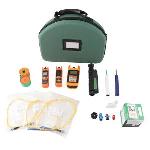
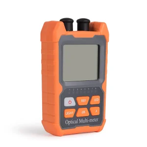
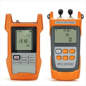
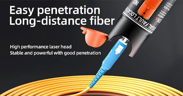
Modern networks mix copper and fiber, so a complete test kit spans both. Aevumix supplies network and optical communication test equipment — from Ethernet cable testers to optical power meters, light sources, and OTDRs. If you would like help choosing the right testers for your network, contact our team.
FAQs
What Is the Difference Between a Network and an Ethernet Cable Tester?
They are the same tool. “Ethernet cable tester” simply emphasizes RJ45 copper Ethernet, while “network cable tester” is the broader term. Both check continuity and wiremap, and advanced models verify T568A/T568B sequencing and performance.
How Do I Read a Wiremap Result?
A pass shows all eight pins mapping in the correct order at both ends with pairs preserved. A missing pin is an open, two linked pins is a short, out-of-order pins are crossed or reversed pairs, and correct continuity with wrong pairing is a split pair.
Do I Have to Use T568A or T568B?
You can use either, but both ends of a straight-through cable must match. A network cable tester confirms the termination follows a consistent standard and flags cables where conductors are in the wrong positions.
Can I Test a Cable That Is Plugged In?
Not for continuity or wiremap. Disconnect the cable from all equipment first, because a tester’s signal can damage a live switch port. Only performance validation is done on active links.
Why Test Ethernet Cabling Before Configuring the Network?
Because proving the physical cabling is sound eliminates the most common hidden cause of network faults. Confirming continuity and wiremap first saves you from troubleshooting switches, VLANs, or IP settings when the real issue is a bad wire.