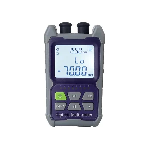
The optical power meter is the most fundamental measuring instrument in fiber optics, and understanding how it works explains why it is so central to testing. This guide covers the working principle of an optical power meter — the photodiode at its heart, how it converts light to a reading, and the key ideas of calibration and referencing. (For step-by-step usage and reading interpretation, see our guides on how to use an optical power meter and power meter readings explained.)
What an Optical Power Meter Does
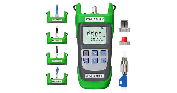
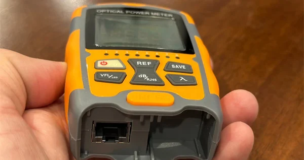
An optical power meter (OPM) measures the power of light in an optical fiber — how much optical energy is arriving, expressed in dBm (absolute power) or dB (relative to a reference). It answers the essential questions of fiber testing: is there enough light, and how much is being lost? Paired with a light source, it measures a link’s insertion loss; on its own, it verifies a transmitter’s output or a received signal level.
The Core Working Principle: The Photodiode
At the heart of every optical power meter is a photodiode — a semiconductor detector that converts light into electrical current. The principle is direct: when light from the fiber strikes the photodiode, it generates a current proportional to the optical power hitting it. The more light, the more current. This is the fundamental conversion that makes measurement possible.
From there, the signal is processed in stages: the small photodiode current is converted to a voltage and amplified by a transimpedance amplifier, then digitized by an analog-to-digital converter, and finally processed and shown on the display as a power value. In essence, the OPM is a calibrated chain that turns photons into a number.
Why Wavelength Matters
A photodiode does not respond equally to all wavelengths — its sensitivity (responsivity) varies with the color of the light. This is why you must set the OPM to the wavelength you are measuring (such as 850, 1310, or 1550 nm). Telling the meter the correct wavelength lets it apply the right calibration factor for the photodiode’s response at that wavelength, so the reading is accurate. Measuring 1550 nm light with the meter set to 1310 nm gives a wrong result, because the responsivity correction is off. Matching the wavelength setting to the source is one of the most important habits in accurate power measurement.
Detector Materials
The photodiode material determines which wavelengths a meter handles well:
| Detector | Typical Wavelength Range | Common Use |
| Silicon (Si) | Around 850 nm | Shorter-wavelength multimode |
| Germanium (Ge) | Broad, incl. 1310/1550 nm | General fiber testing |
| InGaAs | 1310/1550 nm, stable | Telecom single-mode, precise work |
InGaAs detectors are common in telecom power meters for their flat, stable response at the key single-mode wavelengths.
Calibration: Turning Current Into an Accurate Reading
A raw photodiode current is only meaningful if the meter is calibrated. During calibration, the meter’s response is matched to known reference power levels at specific wavelengths, so the electrical signal maps correctly to an optical power value. This is why power meters need periodic recalibration — the photodiode’s response and the electronics can drift over time and with temperature, and calibration keeps the readings trustworthy. A well-calibrated meter is what allows different technicians and instruments to agree on a measurement.
Referencing: Measuring Loss in dB
To measure a link’s insertion loss rather than just absolute power, the OPM uses referencing. First, with a light source connected through reference test cords, you set a reference — the meter records the launch power as “zero dB.” Then you insert the link under test and read the drop; the difference is the insertion loss in dB. This relative measurement is the basis of Tier 1 certification. The working principle here is simple subtraction in the logarithmic dB domain: reference power minus measured power equals loss. Getting the reference method right is essential, which is why it is central to loss testing.
Absolute (dBm) vs Relative (dB)
Understanding the two units clarifies what the meter reports. dBm is absolute optical power referenced to one milliwatt — useful for checking a transmitter’s output or a received level against a system’s power budget. dB is relative, expressing loss compared to the reference you set — useful for insertion-loss testing. The same photodiode principle underlies both; the difference is whether the reading is compared to a fixed one-milliwatt standard or to your own reference measurement.
Sensitivity and Dynamic Range
Two performance characteristics follow directly from the photodiode principle and are worth understanding when choosing a meter. Sensitivity refers to the lowest optical power the meter can detect reliably; it is set by how much current the photodiode produces from very faint light and how well the electronics distinguish that tiny signal from noise. Dynamic range is the span between the weakest and strongest power the meter can measure accurately — from a faint received signal to a strong transmitter output — without the detector saturating. A meter used for long single-mode links needs good low-power sensitivity to read faint far-end signals, while one used near transmitters needs headroom at the high end. Because both traits depend on the detector material and the calibrated electronics behind it, they are specified for each meter, and matching them to the power levels you actually work with is what keeps readings accurate across the whole range of your measurements.
Why the Principle Matters in Practice
Knowing how the OPM works prevents common errors. Because responsivity is wavelength-dependent, you always match the wavelength setting to the source. Because the photodiode and electronics drift, you keep the meter calibrated. Because loss is a relative measurement, you set a proper reference with good test cords. And because contamination on a connector reduces the light reaching the photodiode, you inspect and clean before measuring. Each of these habits follows directly from the underlying principle.
Keeping Measurements Accurate
Because the whole measurement rests on a calibrated photodiode converting light to a reading, a few practices protect that accuracy in daily use. Keep the detector port clean and capped when not in use, since dust on the detector window scatters light just as contamination on a connector does. Inspect and clean the connector you are measuring before every reading, as a dirty end face reduces the light reaching the photodiode and understates the true power. Let the meter and source stabilize before referencing, and avoid measuring across large temperature swings that shift the electronics. Send the meter for periodic recalibration on the manufacturer’s schedule so drift is corrected against known standards. And always confirm the wavelength setting matches the source before trusting a number. None of these steps is complicated, but together they are what separate a meter that gives repeatable, defensible readings from one whose numbers slowly wander out of trust.
Get the Right Optical Power Meter
A quality, well-calibrated meter is the foundation of reliable fiber testing. Aevumix supplies optical power meters, light sources, PON meters, VFLs, and OTDRs for single-mode and multimode networks, along with inspection and cleaning tools. If you would like help choosing a power meter for your wavelengths and applications, contact our team.
FAQs
What Is the Working Principle of an Optical Power Meter?
A photodiode converts incoming light into an electrical current proportional to the optical power. That current is amplified, digitized, and displayed as a power reading in dBm or dB, using a wavelength-specific calibration for accuracy.
Why Do I Set the Wavelength on a Power Meter?
Because a photodiode’s sensitivity varies with wavelength. Setting the correct wavelength applies the right calibration factor for the detector’s response, so the reading is accurate. A wrong setting gives a wrong result.
What Detector Does an Optical Power Meter Use?
A photodiode — commonly silicon for around 850 nm, or germanium and InGaAs for 1310 and 1550 nm. InGaAs is favored in telecom meters for its stable, flat response at single-mode wavelengths.
What Is the Difference Between dBm and dB on a Power Meter?
dBm is absolute power referenced to one milliwatt, used to check output or received levels. dB is relative, expressing loss compared to a reference you set, used for insertion-loss testing. The same photodiode principle produces both.
Why Do Power Meters Need Calibration?
The photodiode’s response and the electronics drift over time and with temperature. Periodic calibration matches the meter to known reference levels so readings stay accurate and consistent across instruments and technicians.